Oct 19, 2026Resources
Why Do Instrumentation Tube Fittings Leak? Common Causes and How to Prevent Them
Learn why instrumentation tube fittings leak, including installation errors, tubing defects, incorrect wall thickness, vibration and damaged components—and what to check before replacing a fitting.
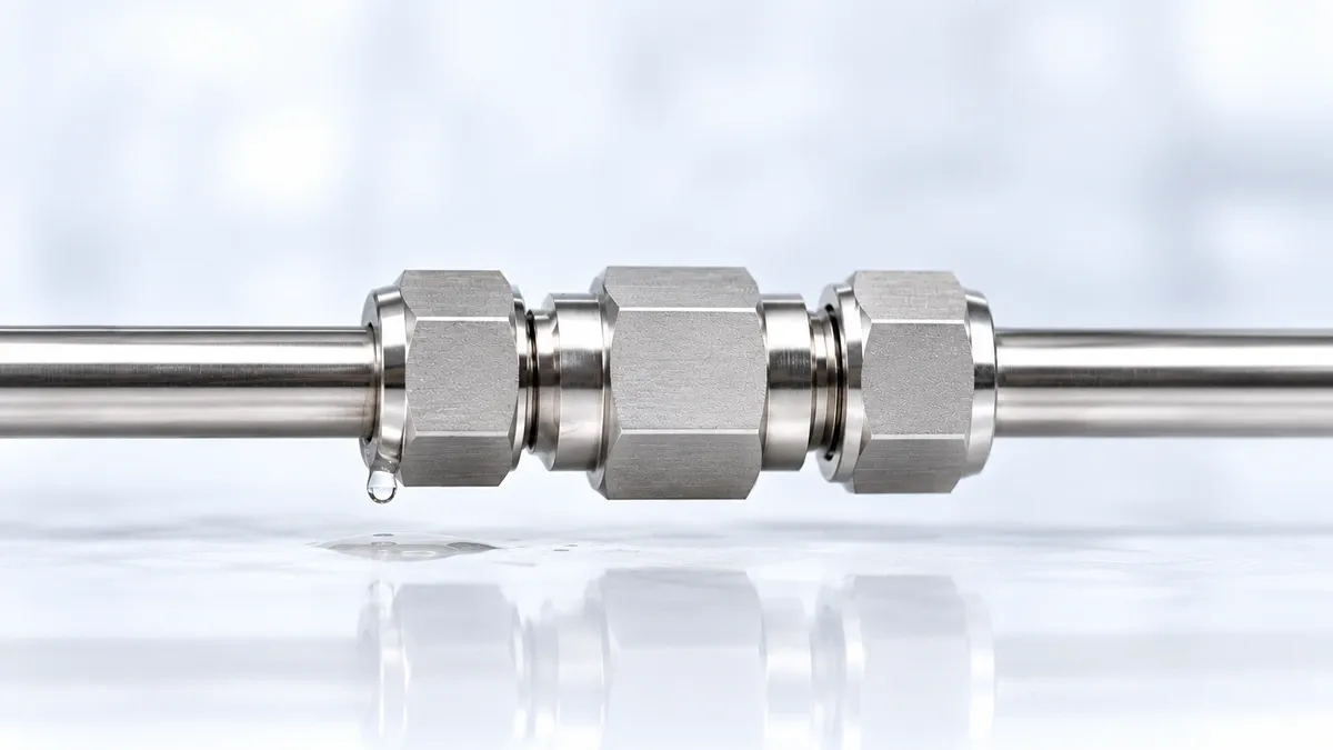
A leaking instrumentation tube fitting does not automatically mean the fitting itself is defective.
The leak path may originate from the tubing, installation, fitting components, system vibration, operating conditions, or even a nearby threaded connection.
That distinction matters when troubleshooting.
Simply tightening a leaking connection again may not solve the underlying problem—and excessive tightening can create additional damage.
This guide explains the most common causes of instrumentation tube fitting leakage, what to inspect first, and what information to collect before replacing components.
1. First Identify Where the Leak Is Actually Coming From
Before adjusting the fitting, determine the location of the leak.
A typical tube fitting assembly can have several potential leak paths:
- between the tubing and ferrule sealing area;
- between fitting components;
- from a threaded end connected to another component;
- through damaged tubing close to the fitting;
- from another nearby valve, adapter, or connection.
This is important because a leak observed around a tube fitting does not necessarily mean the tube-to-fitting connection is responsible.
For example, tightening the tube nut will not correct a leak originating from an NPT threaded connection on the opposite side of an adapter.
Troubleshooting should start with the leak path—not with additional tightening.
2. The Tubing Was Not Fully Inserted Before Assembly
For a compression-style instrumentation tube fitting to assemble correctly, the tubing needs to be positioned properly inside the fitting.
If the tube is not fully inserted to the fitting's internal stop before assembly, the ferrules may engage the tubing in an unintended position.
Possible consequences include:
- incomplete sealing;
- inadequate tube grip;
- inconsistent assembly;
- tube movement under pressure or vibration.
Manufacturer installation guidance commonly emphasizes ensuring that the tube is fully inserted before final make-up. Swagelok
What to check
Before assembly:
- Cut and prepare the tubing correctly.
- Insert the tube fully into the fitting.
- Confirm that it is properly seated.
- Follow the installation procedure specified for that fitting system.
Do not rely only on how the nut “feels” during tightening.
Tubing size, wall thickness, hardness and other variables can change the force experienced during assembly. Swagelok
3. The Fitting Was Under-Tightened
Insufficient make-up is one of the possible causes of leakage in mechanical tube fitting systems.
If the fitting is not assembled sufficiently, the ferrules may not develop the intended sealing and gripping action.
This can result in:
- leakage during initial pressurization;
- inadequate tube retention;
- connection instability during service.
However, there is an important distinction:
“Tight enough” should be determined by the fitting manufacturer's installation procedure—not by a universal torque or number of turns copied from another brand.
Different fitting designs and sizes may use different assembly methods.
What to do
Use the installation instructions for the actual fitting series being installed.
If a connection leaks after installation, first verify:
- fitting type and size;
- tubing OD and wall thickness;
- whether the tubing was fully inserted;
- whether the original assembly procedure was followed.
Do not assume that additional tightening is automatically the correct repair.
4. Over-Tightening Can Also Cause Problems
A common response to a leak is:
“Tighten it more.”
That is not always the correct answer.
Excessive make-up can deform or damage components and may prevent the fitting from sealing as intended. Troubleshooting guidance for tube connections specifically identifies excessive presetting or damaged components as possible causes when a fitting remains tight but still leaks. Parker Hannifin Corporation
This is especially important when technicians repeatedly tighten a connection without first identifying why it leaked.
If the nut is already tight but the connection still leaks
Inspect for:
- damaged ferrules;
- scratched or deformed tubing;
- cracked tubing;
- damaged fitting surfaces;
- incorrect assembly;
- incompatible components.
Replacing a damaged component may be more appropriate than continuing to tighten it.
5. Scratched, Dented or Poor-Quality Tubing Can Create a Leak Path
A compression tube fitting seals against the outside surface of the tubing.
That means tube surface condition matters.
Deep longitudinal scratches, draw marks, dents, visible seams, corrosion or other defects in the sealing area can interfere with sealing.
Industry tubing guidance specifically identifies surface finish and scratches as factors that can create potential leak paths. Swagelok Northwest
Inspect the tube where the ferrules will contact it
Look for:
- longitudinal scratches;
- dents;
- flat spots;
- corrosion or pitting;
- visible weld irregularities;
- damaged coating or plating;
- other surface discontinuities.
A high-quality fitting cannot always compensate for unsuitable tubing.
6. Poor Tube Cutting and Deburring Can Cause Installation Problems
Tube preparation starts before the tube enters the fitting.
A poorly cut tube end can make correct insertion and assembly more difficult.
Burrs are another concern.
External burrs can interfere with assembly or damage components, while internal burrs can break loose and contaminate downstream equipment. Proper deburring is therefore part of preparing tubing for a reliable connection. Swagelok
Good preparation practice includes
- making a clean cut;
- avoiding excessive tube deformation during cutting;
- removing burrs;
- keeping the sealing area clean;
- inspecting the tube before insertion.
Do not use severely damaged tubing simply because it still fits into the nut.
7. Tubing Hardness May Be Incompatible With the Fitting
Ferrules need to interact mechanically with the tubing surface.
If the tubing is too hard for the fitting design, the ferrules may not grip or seal as intended.
Conversely, tubing that is too soft or otherwise unsuitable may deform excessively.
This is why material name alone is not enough.
Two tubes both described as “stainless steel” can differ in:
- material grade;
- manufacturing condition;
- hardness;
- dimensional tolerance;
- surface finish.
Industry guidance therefore treats tubing hardness and material condition as important selection variables. Parker Hannifin Corporation
Before ordering tubing and fittings separately
Verify:
- tubing material;
- material condition;
- applicable tubing specification;
- OD;
- wall thickness;
- hardness requirements;
- fitting manufacturer's tubing recommendations.
Do not assume every stainless steel tube is automatically suitable for every stainless steel compression fitting.
8. Incorrect Wall Thickness Can Affect Connection Performance
Wall thickness affects more than tubing pressure capability.
It also changes how the tubing behaves when the ferrules apply radial force during assembly.
Very thin-wall tubing may be more susceptible to deformation or collapse, while extremely heavy-wall tubing may behave differently during ferrule engagement. Manufacturer guidance therefore considers wall thickness together with pressure, vibration, shock and tubing condition. Parker Hannifin Corporation
For example, two tubes may both be:
1/2 in. OD
but one may have:
0.035 in. wall
and another:
0.065 in. wall
They should not automatically be treated as interchangeable merely because the outside diameter is the same.
This is one reason an RFQ should specify both:
Tube OD + wall thickness
rather than only “1/2-inch tubing.”
9. Tube OD, Ovality and Dimensional Tolerance Matter
Nominal tube size does not mean every tube has identical geometry.
Tubing can vary in:
- outside diameter;
- ovality;
- wall thickness;
- concentricity.
Excessive ovality or dimensional variation can interfere with proper fitting assembly and sealing. Industry tubing guidance specifically warns that tubing outside suitable OD or ovality tolerances may not fit or perform correctly. Swagelok Northwest
A tube that is difficult to insert should therefore not simply be forced into the fitting.
Instead, check the tubing dimensions and condition.
10. Mixing Fitting Components Can Create Compatibility Problems
Two compression fittings may look similar without being dimensionally or mechanically identical.
Differences may exist in:
- ferrule geometry;
- body seat geometry;
- nut dimensions;
- material hardness;
- surface treatment;
- manufacturing tolerances;
- assembly procedure.
For that reason, visually similar nuts, ferrules and bodies should not automatically be assumed interchangeable.
The same caution applies when replacing only part of an existing connection.
Before mixing components, ask:
- Who manufactured the existing fitting?
- What fitting series is it?
- Is the replacement component explicitly approved as compatible?
- Has the combination been technically validated?
If compatibility cannot be established, treating components as interchangeable creates unnecessary uncertainty in the connection.
11. Vibration Can Turn a Good Connection Into a Future Leak
A connection may pass its initial pressure test and still develop a problem later.
Pumps, compressors, engines and other rotating equipment can transmit vibration into tubing systems. Repeated movement can concentrate cyclic stress near rigid connection points and contribute to fatigue damage. Swagelok Northern California
In these cases, the problem may not be an immediate ferrule sealing failure.
The tubing itself can eventually crack near the fitting.
If leakage appears after months of operation
Inspect:
- tubing immediately adjacent to the fitting;
- tube supports and clamps;
- unsupported tubing spans;
- vibration sources;
- alignment;
- repeated bending or movement;
- evidence of fatigue cracking.
Simply replacing the fitting without addressing the vibration source may allow the problem to return.
12. Misalignment and Side Load Can Stress the Connection
A tube fitting should connect properly aligned components—not pull poorly aligned tubing into position.
If tubing has to be forced sideways to enter the fitting, residual stress can remain in the assembly.
That stress can become more significant when combined with:
- vibration;
- pressure cycling;
- thermal expansion and contraction;
- equipment movement.
During installation, route and support the tubing so the connection is not being used as a mechanical alignment tool.
13. Pressure and Temperature Still Need to Be Checked
A leak is not always an installation problem.
The connection also needs to be suitable for the actual service conditions.
Check:
- normal working pressure;
- pressure spikes or pulsation;
- operating temperature;
- startup and shutdown conditions;
- tubing rating;
- fitting rating;
- valve and instrument ratings.
The allowable system pressure is determined by the lowest-rated relevant component or condition, not simply by the nominal rating of one fitting.
Temperature can also affect allowable pressure and material behavior.
Therefore:
A fitting that works correctly at one pressure and temperature should not automatically be assumed suitable for another service condition.
14. Corrosion Can Damage the Tubing Near the Fitting
In corrosive environments, leakage may develop because the tubing itself has deteriorated.
Potential causes include:
- external atmospheric corrosion;
- chloride exposure;
- process-fluid incompatibility;
- crevice conditions;
- contamination;
- unsuitable material selection.
Corrosion near the ferrule contact area can compromise a previously sound connection.
When troubleshooting an older installation, inspect more than the fitting nut.
Look at the surrounding tubing and operating environment as well.
15. Gas Service Can Reveal Problems That Liquid Service Does Not
Gas molecules can escape through very small leak paths.
As a result, a connection that appears acceptable in one service condition may require greater attention when used with gases.
For gas systems, pay particular attention to:
- tubing surface quality;
- wall thickness;
- dimensional consistency;
- correct assembly;
- material condition;
- fitting compatibility.
Heavier-wall tubing can, in some fitting systems and applications, provide more support for developing a reliable gas seal, but this should not be interpreted as a universal rule that “thicker is always better.” Actual suitability depends on the fitting system, tubing and service conditions. Swagelok Northern California
16. Is the Leak Actually Coming From the Thread?
Instrumentation fittings often combine a tube end with another connection type, such as:
- NPT;
- BSPT;
- BSPP;
- metric threads;
- another tube connection.
A leak at the threaded side requires a different diagnosis from a leak at the compression end.
For example:
NPT is a tapered thread system in which the threaded connection participates in sealing.
BSPP is a parallel thread and commonly relies on a separate sealing method depending on the connection design.
Confusing thread standards or sealing methods can create leakage even when the tube fitting side is assembled correctly.
17. A Practical Tube Fitting Leak Troubleshooting Sequence
When a tube connection leaks, avoid random adjustments.
Use a structured inspection sequence.
Step 1 — Make the system safe
Depressurize and isolate the system according to the applicable plant or equipment safety procedure.
Never attempt to tighten, loosen or disassemble a tube fitting while the system is pressurized. Swagelok
Step 2 — Identify the leak location
Determine whether leakage is coming from:
- tube end;
- fitting body;
- thread;
- valve;
- adapter;
- damaged tubing.
Step 3 — Verify the specification
Check:
- tube OD;
- wall thickness;
- tubing material;
- fitting material;
- fitting type;
- connection type.
Step 4 — Inspect the tubing
Look for:
- scratches;
- burrs;
- dents;
- ovality;
- corrosion;
- cracks;
- deformation.
Step 5 — Review the original assembly
Was the tube fully inserted?
Was the correct installation procedure used?
Were the correct components installed?
Step 6 — Check operating conditions
Compare the actual:
- pressure;
- temperature;
- media;
- vibration;
- pressure cycling
with the specified system conditions.
Step 7 — Inspect for component damage
If the connection has already been repeatedly tightened, disassembled or subjected to abnormal conditions, inspect the components before deciding whether they can remain in service.
18. Quick Troubleshooting Table
Symptom | Possible Cause | What to Check |
|---|---|---|
Leaks immediately after installation | Incorrect assembly or incomplete tube insertion | Installation procedure and tube position |
Nut is tight but fitting still leaks | Damaged tube, ferrules or sealing surfaces | Disassemble safely and inspect |
Leak develops after operating for some time | Vibration, fatigue, corrosion or cycling | Tubing near fitting and system conditions |
Tube is difficult to insert | OD/ovality issue, burr or damaged tube | Tube dimensions and surface |
Tube deforms during assembly | Wall thickness/material condition may be unsuitable | Tubing specification and fitting requirements |
Gas system has persistent small leak | Surface finish, assembly or tubing selection | Tubing and fitting compatibility |
Leak appears near adapter thread | Thread/sealing issue rather than tube end | Thread standard and sealing method |
Repeated leakage at the same location | System-level cause may remain | Alignment, vibration, supports and operating conditions |
The table is a troubleshooting starting point—not a substitute for the fitting manufacturer's instructions or the system designer's requirements.
19. What Information Should You Send When Asking for Help?
“1/2-inch fitting is leaking” is usually not enough information to diagnose the problem.
A more useful technical inquiry includes:
Tubing
- OD
- wall thickness
- material
- specification if known
- seamless or welded
- hardness/condition if available
Fitting
- fitting type
- material
- manufacturer/series if replacing an existing fitting
- tube connection size
- thread or opposite-end connection
Service
- media
- working pressure
- maximum pressure
- operating temperature
- vibration or pulsation
Problem
- when the leak began
- exact leak location
- whether the connection has been reassembled
- clear photos of the fitting and tubing
- drawing or BOM if available
This information can help distinguish a component problem from a tubing, installation or system-design problem.
Frequently Asked Questions
Can I stop a leaking tube fitting by tightening it more?
Not necessarily.
If insufficient assembly is the cause, correct make-up may resolve the problem—but repeated tightening without diagnosis can damage components. Follow the fitting manufacturer's procedure and inspect the connection if leakage persists.
Can scratched tubing cause a compression fitting to leak?
Yes. Because the fitting seals against the tubing OD, significant scratches or other surface defects in the sealing area can create potential leak paths. Swagelok Northwest
Can I use the same fitting with different tubing wall thicknesses?
Possibly, but compatibility should be verified.
Tube OD alone is not enough. Wall thickness, material, hardness, pressure, temperature and the fitting manufacturer's tubing requirements should also be considered.
Why does a fitting leak only after the machine has been running?
Vibration, cyclic loading, thermal movement, corrosion or tubing fatigue may contribute to leakage that develops over time. Inspect the tubing around the connection as well as the fitting itself.
Can I mix ferrules and nuts from different tube fitting brands?
Do not assume visually similar components are interchangeable. Verify compatibility before mixing fitting bodies, nuts or ferrules from different systems.
Does a leaking fitting always need to be replaced?
No. The correct action depends on the cause and condition of the components. The leak may originate from tubing, installation, threads or system conditions rather than a defective fitting. Damaged components, however, should not simply be returned to service without appropriate evaluation.
Preventing Tube Fitting Leaks Starts Before Installation
Reliable instrumentation connections depend on more than selecting a fitting with the correct nominal size.
The complete connection includes:
fitting + tubing + assembly + operating conditions + system support.
Before installation, verify the tubing OD, wall thickness, material and condition. Prepare the tube correctly, use compatible components, and follow the installation procedure for the actual fitting system.
If a leak develops later, identify the leak path before tightening or replacing anything.
That approach is usually more effective than treating every leak as a loose fitting.
Need Help Reviewing a Tube Fitting Application?
For a new project or replacement requirement, send StarkValve:
- tube OD and wall thickness;
- fitting type and connection;
- material;
- working pressure;
- operating temperature;
- process media;
- quantity;
- existing part number, drawing or BOM if available.
We can review the information against the available fitting configuration before quotation.