Oct 21, 2026Resources
How to Choose a Quick Coupling: Pressure, Flow, Media & Connection
Learn how to choose a quick coupling based on pressure, flow, media, temperature, shutoff type, seals and end connections—and avoid common selection mistakes.
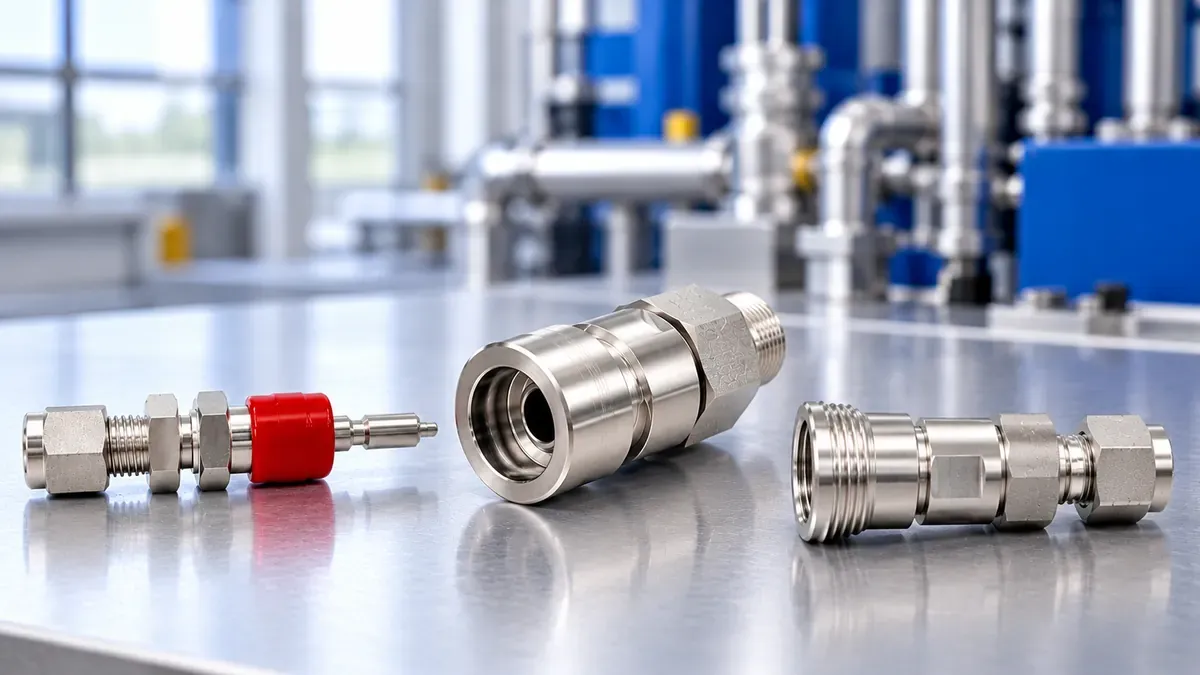
Quick couplings make it faster to connect and disconnect fluid lines, but selecting the right one involves much more than matching the thread size.
Two couplings that look similar may differ significantly in working pressure, internal flow path, shutoff arrangement, seal material, end connection and mating interface. A coupling that physically connects to the equipment may still be wrong for the application's pressure, flow, media or temperature.
The safest approach is to start with the system requirements and then select the coupling.
This guide explains the key factors engineers, distributors and industrial buyers should check before specifying or replacing a quick coupling.
1. Start With the Application, Not the Part Number
Before comparing coupling models, define what the connection actually needs to do.
Start with these questions:
- What fluid or gas will pass through the coupling?
- What is the normal operating pressure?
- What is the maximum system pressure?
- Are pressure spikes or pulsation possible?
- What are the media and ambient temperatures?
- What flow rate is required?
- How much pressure drop is acceptable?
- Should one side, both sides or neither side shut off when disconnected?
- Is fluid loss during disconnection important?
- Is air inclusion during reconnection important?
- Will residual pressure remain when connecting or disconnecting?
- How frequently will the coupling be operated?
- What end connection is required?
- Does it need to mate with an existing coupling?
A request such as “1/2-inch stainless steel quick coupling” does not provide enough information for reliable selection.
Define the application first. Then select the coupling.
2. Coupling Size Is Not the Same as Connection Size
One of the most common specification mistakes is treating coupling size, thread size and tube or hose size as if they were the same thing.
They are separate characteristics.
Coupling body or interface size describes the mating coupling mechanism.
End connection size describes how the coupling connects to the rest of the system.
Tube or hose size describes the line attached to the coupling.
Internal flow passage determines how much restriction the coupling introduces.
Different end connections can therefore be offered on the same coupling body size.
When replacing an existing coupling, do not specify only:
1/2-inch quick coupling
Instead, identify as much as possible:
- coupling body or series;
- coupler or stem;
- end connection type;
- end connection size;
- tube or hose size;
- existing mating component;
- existing part number, if available.
Clear photos and dimensional information can also help when the original part number is unknown.
3. Check Working Pressure Against the Actual System
Quick couplings are pressure-containing components, so pressure capability must be checked against the actual operating conditions.
Important values can include:
- normal working pressure;
- maximum system pressure;
- pressure spikes or pulsation;
- pressure present during connection or disconnection.
Do not select a coupling simply because its pressure rating is higher than the machine's normal operating pressure.
The maximum expected system condition also matters.
Working Pressure Is Not Burst Pressure
Working pressure and burst pressure are not interchangeable.
Working pressure defines the pressure capability intended for operation under the manufacturer's specified conditions.
Burst pressure relates to failure under specified test conditions and should not be treated as allowable operating pressure.
The allowable pressure of a complete fluid system also depends on the relevant ratings of the connected hose, tubing, fittings, valves, threads and other components.
A high-pressure coupling does not automatically make the entire assembly suitable for the same pressure.
Quick Coupling Pressure Ranges
Different coupling designs are intended for different pressure requirements.
For example, available quick coupling series may offer maximum working pressures up to:
Series | Maximum Working Pressure |
|---|---|
QC | Up to 207 bar (3000 psig) |
QM | Up to 276 bar (4000 psig) |
QF | Up to 414 bar (6000 psig) |
These are maximum series-level values. The allowable working pressure for a specific coupling should always be verified for the actual size, material, end connection and operating conditions.
4. Do Not Select Flow Performance From Nominal Size Alone
A coupling creates a restriction in the fluid path.
Its internal geometry may include:
- valves;
- springs;
- seals;
- stems;
- reduced passages;
- changes in flow area.
This means two couplings with similar nominal connection sizes do not necessarily provide the same flow performance.
When flow matters, useful parameters can include:
- flow coefficient;
- minimum bore;
- required flow rate;
- allowable pressure drop;
- fluid properties.
A coupling may meet the pressure requirement and still be unsuitable if it creates excessive restriction at the required flow.
That is why selecting only by thread size can be misleading.
5. Why Pressure Drop Matters
Pressure drop is the reduction in fluid pressure as the fluid passes through a restriction.
Every hose, fitting, valve and coupling can contribute resistance to the system.
If a quick coupling is too restrictive for the required flow, excessive pressure drop can contribute to:
- reduced available pressure downstream;
- restricted flow;
- slower actuator response;
- increased fluid velocity through the restriction;
- additional heat generation;
- reduced system efficiency.
For applications where flow performance is important, ask:
What flow is required, and what pressure drop across the coupling is acceptable?
This is more useful than choosing the coupling from nominal size alone.
6. Choose the Required Shutoff Function
Another important selection factor is what should happen when the coupling is disconnected.
Depending on the coupling design, common configurations include full flow, single-end shutoff and double-end shutoff.
Full Flow
A full-flow or non-valved configuration provides an open flow path without automatic shutoff valves at the coupling interface.
This can be useful where low restriction and an open internal passage are priorities and the system can be isolated elsewhere before disconnection.
For example, QF full-flow configurations use a smooth, open internal flow path without valves at either end.
Single-End Shutoff — SESO
With single-end shutoff, one side incorporates automatic shutoff when the connection is separated.
This can be useful when only one side needs to retain the media after disconnection.
Double-End Shutoff — DESO
With double-end shutoff, both sides incorporate shutoff functionality.
This can help control fluid release from both sides of the disconnected line.
The best configuration depends on what the system needs to do during and after disconnection.
Do not automatically assume that more shutoff valves are always better. Internal valving can also affect the flow path and pressure drop.
7. Media Compatibility Means More Than Body Material
A common RFQ may specify:
316 stainless steel quick coupling
That is useful information, but it does not completely define media compatibility.
Depending on the design, the fluid may contact:
- body components;
- stem components;
- valves;
- O-rings;
- other seals;
- internal metallic components.
Quick coupling configurations can be available with different body and seal materials. For example, stainless steel and brass body-component options may be combined with seal materials such as FKM or nitrile rubber depending on the configuration.
The body material alone therefore does not establish compatibility with the process media.
When requesting a coupling, specify the actual media whenever possible, such as:
- hydraulic oil;
- water;
- compressed air;
- inert gas;
- glycol mixture;
- fuel;
- chemical process fluid.
The complete wetted-material and seal combination should then be evaluated for the actual service.
8. Temperature and Media Should Be Evaluated Together
Temperature can affect both sealing performance and material suitability.
It can influence:
- seal properties;
- leakage performance;
- fluid viscosity;
- pressure capability;
- material behavior;
- service life.
Both media temperature and ambient temperature may matter.
For that reason, avoid specifying only:
stainless steel + 200 bar + 1/2-inch thread
A more useful specification would include:
media + working pressure + maximum pressure + temperature + connection + material requirement
The exact coupling and seal combination can then be checked for the application.
9. End Connection Is Separate From Coupling Interface
The coupling interface determines how the two coupling halves mate.
The end connection determines how the coupling connects to the tube, hose or equipment.
These are separate specifications.
Depending on the coupling series, available end connections may include:
- other specified hydraulic connections.
For example, a coupling may have a particular body size while being available with more than one threaded or tube connection.
Therefore:
A 1/2-inch quick coupling is not automatically a 1/2-inch NPT quick coupling.
Always identify both the coupling interface and the equipment-side connection.
10. Residual Pressure Is a Separate Selection Requirement
A coupling may have sufficient working-pressure capability once connected but still be difficult or unsuitable to connect when pressure remains trapped in the line.
Residual pressure can result from:
- trapped hydraulic fluid;
- thermal expansion;
- stored mechanical loads;
- attachment movement;
- system design.
The normal working-pressure rating does not automatically mean that the coupling can be connected or disconnected under residual pressure.
If pressure may remain on either side during connection or disconnection, state this explicitly when selecting the coupling.
This is especially important for mobile hydraulic equipment and other systems where trapped pressure is common.
11. Fluid Loss and Air Inclusion Can Matter
For some applications, a small amount of fluid released during disconnection may not be important.
For others, it can affect:
- cleanliness;
- operator exposure;
- environmental control;
- process-fluid loss;
- maintenance;
- contamination.
Air entering the system during reconnection can also matter in certain applications.
For specified double-end shutoff QC configurations, representative catalogue values include:
Series | Spillage | Air Inclusion |
|---|---|---|
QC4 | 0.3 cm³ | 0.3 cm³ |
QC6 | 1.0 cm³ | 1.0 cm³ |
QC8 | 3.0 cm³ | 3.0 cm³ |
These values apply to the specified DESO configurations and should not be generalized to every coupling type or configuration.
If low fluid loss or low air inclusion is important, include that requirement in the RFQ rather than assuming every shutoff coupling behaves the same way.
12. Interchangeability Must Be Verified, Not Assumed
Two couplings may:
- look similar;
- have the same nominal size;
- use the same thread size;
- and even appear to connect;
without necessarily being the correct mating combination.
Interchangeability can depend on:
- mating dimensions;
- coupling profile;
- locking mechanism;
- valve actuation;
- seal location;
- body size;
- pressure capability;
- flow performance.
Some coupling series are designed to interchange with corresponding products from other manufacturers, but compatibility should still be verified for the specific mating series or existing part.
When replacing an existing coupling, provide as much information as possible:
- existing manufacturer;
- series;
- part number;
- dimensions;
- clear photos;
- drawing or sample.
Physical engagement alone should not be treated as proof of safe interchangeability.
13. Consider How Often the Coupling Will Be Used
A coupling connected once during equipment installation experiences a different duty cycle from one connected and disconnected several times every shift.
Connection frequency can affect the importance of:
- operating convenience;
- locking mechanism;
- seal wear;
- contamination control;
- fluid loss;
- residual-pressure capability;
- maintenance frequency.
If the coupling will be operated frequently, state that requirement during selection.
It may affect which design is most appropriate for the application.
14. Consider Vibration, Side Load and Operating Environment
Catalog pressure and flow data do not describe every real operating condition.
A coupling may be installed on:
- mobile hydraulic machinery;
- vibrating equipment;
- outdoor equipment;
- dirty environments;
- washdown systems;
- corrosive environments;
- moving hoses or assemblies.
Vibration, side loading, contamination and mechanical movement can all influence connection reliability and service life.
These conditions should therefore be considered alongside pressure, flow and media.
A coupling suitable for a clean indoor test stand may not be the best choice for exposed mobile equipment even when the nominal pressure and connection size are the same.
15. Common Quick Coupling Selection Mistakes
Several specification mistakes repeatedly create problems when quick couplings are selected or replaced.
Mistake 1: Ordering by Thread Size Only
“1/2-inch thread” does not fully define the coupling.
The mating interface, body size, thread standard, flow and operating requirements also matter.
Mistake 2: Assuming the Same Nominal Size Means the Same Flow
Internal geometry varies between coupling designs.
Compare flow coefficient, minimum bore or pressure-drop data when flow performance matters.
Mistake 3: Using Burst Pressure as Working Pressure
Burst pressure should not be treated as allowable operating pressure.
Use the verified working-pressure rating for the selected configuration.
Mistake 4: Specifying Only the Body Material
“316 stainless steel” does not establish compatibility for seals and other wetted components.
Specify the actual media and temperature.
Mistake 5: Ignoring the Shutoff Arrangement
Full-flow, single-end shutoff and double-end shutoff configurations perform different functions during disconnection.
Specify what should happen on each side when the coupling is separated.
Mistake 6: Assuming Two Couplings Are Interchangeable Because They Connect
Physical connection alone does not prove correct interchangeability.
Verify the coupling series, mating dimensions or existing part information.
Mistake 7: Ignoring Residual Pressure
Working-pressure capability does not automatically establish connect-under-pressure capability.
State whether trapped pressure may be present during connection or disconnection.
Mistake 8: Ignoring Pressure Drop
A coupling can meet the required pressure rating and still restrict a high-flow circuit.
Pressure capability and flow performance should be evaluated separately.
16. A Practical Quick Coupling Selection Sequence
A structured selection process reduces the chance of choosing a coupling from one specification alone.
Step 1 — Define the Application
Identify the equipment and what the coupling needs to do.
Step 2 — Identify the Media
Specify the actual fluid or gas.
Step 3 — Define Pressure Conditions
Provide:
- normal working pressure;
- maximum system pressure;
- known pressure spikes or pulsation;
- residual pressure during connection, if applicable.
Step 4 — Define Temperature
Provide the media temperature and, where relevant, ambient temperature.
Step 5 — Determine Required Flow
Provide normal and maximum flow where known.
If pressure drop is important, state the acceptable limit.
Step 6 — Select the Shutoff Function
Determine whether the application needs:
- full flow;
- single-end shutoff;
- double-end shutoff.
Step 7 — Select Materials and Seals
Consider the media, temperature and operating environment rather than body material alone.
Step 8 — Identify the Coupling Interface
Specify the existing mating series, body size or applicable interface requirement.
Step 9 — Specify the End Connection
Identify the exact:
- connection type;
- connection size;
- tube or hose requirement.
Step 10 — Define Special Operating Requirements
Examples include:
- frequent connection and disconnection;
- residual pressure;
- low fluid loss;
- low air inclusion;
- vibration;
- corrosive environment;
- contamination concerns.
Only after these requirements are understood should a specific coupling configuration be selected.
17. Quick Coupling Selection Table
Application Requirement | What to Check |
|---|---|
High working pressure | Verified working-pressure rating |
High flow | Flow coefficient, bore and pressure drop |
Hydraulic pressure spikes | Maximum system and dynamic pressure conditions |
Chemical or process media | Complete wetted materials and seals |
High or low temperature | Seal and material temperature suitability |
Open flow path | Full-flow configuration |
Automatic shutoff | SESO or DESO configuration |
Frequent disconnection | Operating mechanism and durability |
Minimize fluid loss | Spillage performance |
Minimize air entry | Air-inclusion performance |
Existing coupling replacement | Mating interface and interchangeability |
Existing equipment port | Exact end connection and size |
Trapped pressure | Connection/disconnection pressure capability |
Vibration or moving equipment | Mechanical operating conditions |
This table is a screening tool. Final suitability should be verified for the actual coupling configuration and service conditions.
18. What Information Should You Send With an RFQ?
Instead of sending:
Need 100 pcs 1/2" stainless steel quick couplings.
Provide as much of the following information as possible:
Application:
What equipment or system is the coupling used on?
Media:
What fluid or gas passes through it?
Working pressure:
What is the normal operating pressure?
Maximum pressure:
What is the highest expected system pressure?
Flow:
What flow rate is required?
Temperature:
What are the media and ambient temperatures?
Shutoff requirement:
Full flow, single-end shutoff or double-end shutoff?
Body material:
Stainless steel, brass or other specified material?
Seal requirement:
If already defined.
Coupling interface:
Existing series, body size or mating requirement.
End connection:
Exact connection type and size.
Residual pressure:
Will pressure remain during connection or disconnection?
Fluid loss requirement:
Is minimizing spillage important?
Quantity:
How many pieces are required?
Existing part number:
If replacing another coupling.
Photos or drawing:
Especially useful when the existing coupling cannot be clearly identified.
If some information is unknown, say so rather than guessing.
A clear photo plus application details is often more useful than an incomplete specification.
Frequently Asked Questions
Can I choose a quick coupling only by thread size?
No.
Thread size identifies only part of the connection. Coupling interface, body size, pressure, flow, media, temperature, shutoff function and other application requirements may also need to be considered.
Does a larger quick coupling always provide better flow?
Not necessarily.
Actual flow performance depends on internal geometry, bore, valve arrangement and operating conditions. Flow coefficient or pressure-drop data provides a better basis for comparison when flow is important.
Is burst pressure the maximum pressure I can operate at?
No.
Burst pressure should not be treated as allowable working pressure. Use the verified working-pressure rating for the actual coupling configuration and service conditions.
What is the difference between SESO and DESO?
SESO means single-end shutoff, where one side incorporates shutoff functionality.
DESO means double-end shutoff, where both sides incorporate shutoff functionality.
The correct choice depends on how the system should behave when disconnected.
Can stainless steel quick couplings handle any fluid?
No.
Body material alone does not establish chemical compatibility. Seals and other wetted materials, temperature and actual service conditions must also be considered.
Why can't I connect a hydraulic quick coupling when the machine is off?
Pressure may remain trapped in the circuit even when the machine is not operating.
Thermal expansion, stored loads and trapped hydraulic fluid can all create residual pressure.
If connection under residual pressure is required, that should be identified during coupling selection.
Are two quick couplings interchangeable if they physically connect?
Not necessarily.
Correct interchangeability can depend on the mating profile, dimensions, locking mechanism, valve operation and other design characteristics.
Verify the mating series or existing part rather than relying only on physical engagement.
Why can equipment operate more slowly after adding a quick coupling?
One possible cause is excessive pressure drop through the coupling or another restriction in the circuit.
The required flow should be compared with the coupling's flow performance while considering the complete system rather than assuming nominal connection size guarantees adequate flow.
The Best Quick Coupling Is the One That Fits the Application
A quick coupling should not be selected from one specification alone.
A reliable selection considers the complete combination of:
Pressure + Flow + Media + Temperature + Shutoff Function + Materials & Seals + End Connection + Mating Interface + Operating Conditions
For a replacement coupling, start by identifying the existing mating interface.
For a new application, start with the system requirements.
And when flow performance matters, do not stop at nominal size—evaluate the coupling's internal flow characteristics and pressure drop.
Need Help Selecting a Quick Coupling?
Send us your:
- application;
- media;
- working and maximum pressure;
- temperature;
- required flow;
- shutoff requirement;
- coupling type or existing series, if known;
- end connection;
- material requirements;
- quantity;
- existing part number, photos, drawing or BOM.
With complete operating information, the coupling configuration can be reviewed before quotation rather than selected from thread size alone.