
Sep 16, 2026Applications
Test, Measurement & Sampling
Explore fluid connection requirements for test, measurement and sampling systems, including tubing, tube fittings, isolation valves and instrument interfaces.
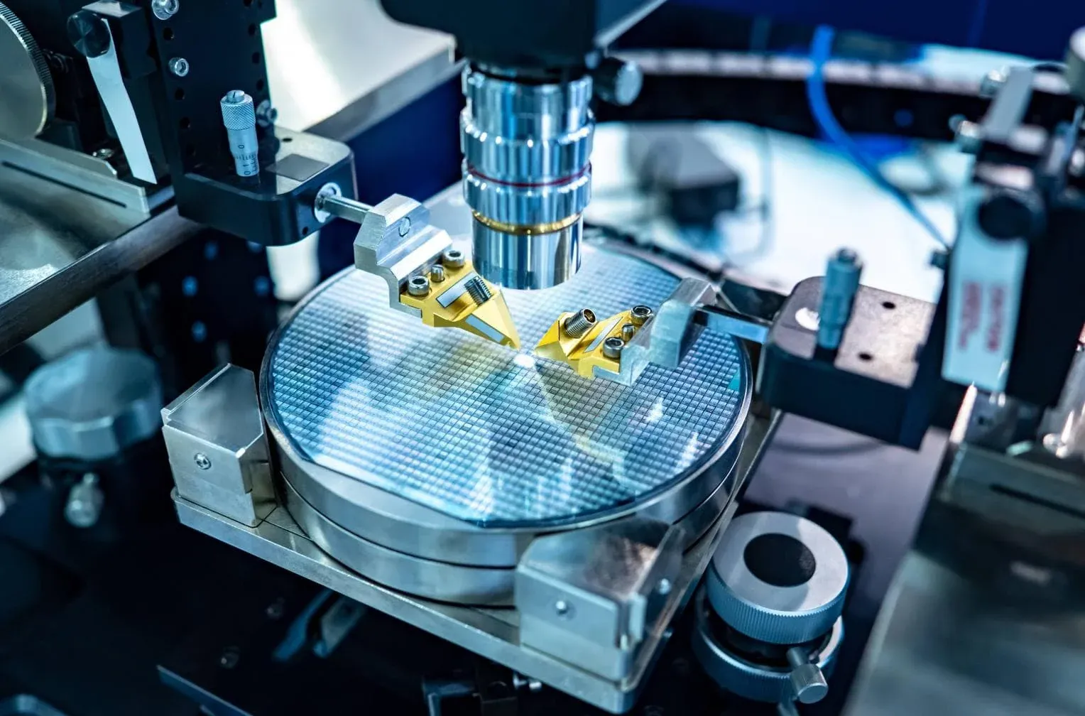
From the Process to the Measurement or Sample Point
Test, measurement and sampling systems create a controlled fluid path between a process or pressure source and the point where the fluid is measured, tested or collected.
Depending on the application, that path may include:
- A process or equipment connection
- Isolation valves
- Tubing
- Tube fittings
- Flow-control components
- Test or measurement instruments
- Sampling or analyzer interfaces
The individual components may be small, but their selection can affect how the measurement or sample is obtained.
The starting point is therefore:
What needs to be measured or sampled, where does the fluid come from, and what conditions exist between the source and the final interface?
CONNECT — Establish the Fluid Path
Tube fittings and adapters connect the different interfaces between the process, tubing, valves and measurement equipment.
Before selecting a connection, identify both sides completely.
Relevant information can include:
- Tube outside diameter
- Thread or connection standard
- Connection size
- Male/female configuration
- Sealing interface
- Material
- Operating pressure
- Operating temperature
- Process medium
A description such as “1/4-inch test fitting” is not enough to establish the actual connection.
The size may refer to tubing, pipe thread or another equipment interface.
ISOLATE — Separate the Instrument or Sample Line
Isolation allows a measurement device, test connection or sample line to be separated from the source when required by the system.
Needle valves and other instrumentation valves may be used where the application requires isolation or controlled flow.
The appropriate valve depends on:
- Required function
- Medium
- Pressure
- Temperature
- Connection
- Material
- Seat, stem or packing materials where applicable
- Required flow characteristics
The valve should be selected from the required operating function rather than from appearance alone.
CONTROL — Manage Flow Where the Application Requires It
Some measurement and sampling applications require more than simple on/off isolation.
The fluid may need to be introduced, restricted, vented, purged or redirected as part of the test or sampling procedure.
Depending on the system, this can involve valves, manifolds or other flow-control components.
Before selecting these components, establish:
source → required function → flow path → final measurement or sample point
This helps distinguish between a connection requirement and a control requirement.
A valve used only for isolation does not necessarily perform the same role as one used for controlled flow.
MEASURE — Connect to the Instrument
Measurement systems can involve pressure gauges, transmitters, test instruments, analyzers or other devices.
The instrument connection may differ from the upstream tubing or process interface.
Adapters or transition fittings may therefore be required.
A complete instrument connection should identify:
connection standard + size + configuration + sealing method
For replacement instruments or test equipment, the existing manufacturer and complete part number can also help identify the interface.
However, part-number matching should not replace confirmation of the actual connection and operating conditions.
SAMPLE — Preserve a Defined Path From Process to Sample Point
Sampling creates an additional requirement: fluid must travel from the process to a defined collection or analysis point.
A basic sample path may include:
process takeoff → isolation → tubing → flow control → sample or analyzer interface
The actual design can be much more complex depending on the process and analysis requirement.
For component procurement, important inputs can include:
- Process medium
- Sample phase
- Pressure
- Temperature
- Tubing size and material
- Connection type
- Isolation requirement
- Required flow path
- Sampling or analyzer interface
The sample system should be evaluated as a fluid path rather than as a collection of unrelated fittings.
Tubing Between the Source and the Instrument
Tubing forms the transfer path between connection points.
Its specification can influence more than mechanical fit.
Depending on the application, buyers may need to consider:
- Tube outside diameter
- Wall thickness
- Material
- Pressure
- Temperature
- Medium
- Routing
- Internal volume
- Surface or cleanliness requirements where specified
In sampling and analytical applications, the tubing path can also influence sample transport. Swagelok's current sampling-system guidance, for example, treats transport time, system volume and representative sampling as important design considerations.
For this reason, tubing dimensions should follow the actual system requirement rather than being selected only because a particular size is readily available.
Sampling Is More Than Connecting a Tube
A technically valid sampling system must deliver a sample that is useful for its intended analysis.
Depending on the process, issues such as sample transport time, phase behavior, pressure and temperature changes, contamination and system volume may affect the result.
These are system-design questions, not properties that can be solved by a fitting alone.
StarkValve's role in this application is therefore focused on the fluid connection and control components used within the required sampling path.
Where a project has specific analytical or sampling-system requirements, those requirements should be established before component selection.
TEST — Define the Test Conditions
Test systems can range from simple pressure measurement connections to more complex test benches and equipment-validation circuits.
The required component depends on the test itself.
Useful inputs can include:
- Test medium
- Test pressure
- Test temperature
- Connection interfaces
- Required isolation
- Required adjustment or control
- Frequency of connection/disconnection
- Instrument interface
- Material requirements
A component suitable for one test circuit should not automatically be assumed suitable for another simply because the connection size is the same.
Temporary and Disconnectable Test Connections
Some test systems require equipment or instruments to be connected and removed repeatedly.
Where appropriate, a quick coupling or another disconnectable interface may be considered.
Selection can depend on:
- Pressure
- Temperature
- Medium
- Required flow
- Connection size
- Seal material
- Valve configuration
- Frequency of connection
- Fluid loss during disconnection where relevant
- Air inclusion where relevant
These performance requirements need to be confirmed against the specific coupling design.
A general quick coupling should not be assumed to meet specialized test requirements without supporting product data.
Common Specification Gaps
“Connection for a pressure gauge”
The instrument connection, pressure, temperature, medium and upstream interface are still required.
“Sampling fitting”
This does not define where the sample originates, where it goes or how the connection fits into the sampling path.
Tube size without wall thickness
Wall thickness may be relevant to the operating requirement and tubing/fitting combination.
Pressure without the test medium
Gas and liquid test systems should not be treated as identical simply because the nominal pressure is the same.
Analyzer connection without process conditions
The upstream medium and operating conditions remain relevant even when the final interface is known.
Existing part number only
A part number is useful evidence, but the required service conditions and interfaces should still be confirmed.
What to Include in a Test, Measurement or Sampling RFQ
Where available, provide:
- Application Pressure measurement, test bench, sampling, analyzer connection, calibration circuit or another function.
- Medium or sample
- Required component Tube fitting, valve, manifold, tubing, adapter, quick coupling or flexible connection.
- Connection details
- Tube dimensions where applicable
- Material
- Operating or test pressure
- Operating or test temperature
- Required function Connection, isolation, adjustment, venting, sampling, measurement or disconnect.
- Quantity
- Instrument or analyzer interface
- Required standards or documentation
- Drawing, P&ID, datasheet or existing part number where available
Unknown parameters should be identified as to be confirmed rather than guessed.
Relevant Component Families
Test, measurement and sampling systems may involve several StarkValve product families:
- Instrumentation Tube Fittings
- Instrumentation Valves & Manifolds
- Instrumentation Tubing
- Quick Couplings where a disconnectable interface is required
- Pipe Fittings
- Hose & Flexible Connections where appropriate
- Related adapters and transition connections
The appropriate components depend on the actual measurement, test or sampling path.
Define the Path Before Selecting the Components
For measurement:
source → isolation → connection → instrument
For sampling:
process → isolation → transport → control → sample or analyzer interface
For testing:
test source → connection/control → component or equipment → measurement
These are different functions even when some of the same fittings, valves and tubing appear in each system.
For project inquiries, send the available drawing, P&ID, instrument information, process conditions and component list together with the required connections.
Define the fluid path first. Then select the components.