
Sep 16, 2026Applications
Liquid Cooling & Thermal Management
Explore fluid connection requirements for liquid cooling and thermal management systems, including quick couplings, hose, tubing and connection interfaces.
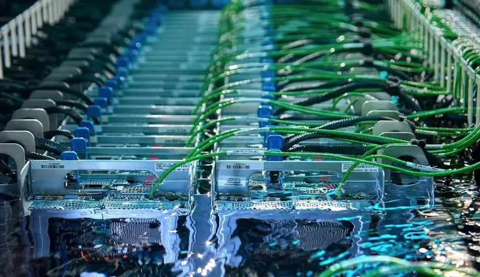
The Fluid Path Behind Liquid Cooling
Liquid cooling and thermal management systems move a coolant between heat-generating equipment and the equipment used to remove that heat.
Depending on the system architecture, the fluid path can include distribution equipment, manifolds, tubing, hose, fittings, valves and disconnectable connections.
In data-center liquid cooling, for example, connection points can exist between coolant distribution units, rack manifolds and IT equipment. Similar fluid-transfer principles can also appear in other industrial thermal-management systems.
For component selection, the starting point should be the actual fluid circuit:
What coolant is being transferred, between which interfaces, at what flow, pressure and temperature, and does the connection need to be permanent or disconnectable?
CONNECT — Define Each Interface
A cooling loop can contain several different connection interfaces.
These may include connections between:
- Tubing and equipment
- Hose and equipment
- Tubing and manifolds
- Hose and manifolds
- Quick couplings and fluid lines
- Threaded or other equipment ports
The connection should be identified completely rather than only by nominal size.
Where relevant, specify:
- Connection type
- Size
- Male/female configuration
- Tubing or hose dimensions
- Sealing interface
- Material
An adapter should be selected by identifying both ends of the connection, not simply by choosing a fitting that appears to have the correct thread.
TRANSFER — Tubing and Hose Carry the Coolant
Tubing and flexible hose provide the fluid path between thermal-management components.
The appropriate choice depends on the system architecture and installation.
Tubing may be suitable for more fixed routing, while flexible hose can be useful where the installation requires movement, tighter routing, service access or connection between equipment that cannot be joined conveniently by rigid tubing.
Relevant specification inputs can include:
- Tube or hose size
- Wall thickness where relevant
- Material
- Overall hose length
- End connections
- Coolant
- Operating pressure
- Operating temperature
- Required flow
- Routing and bend requirements
- Environmental conditions
Current liquid-cooling engineering guidance also emphasizes that hose/tubing material and elastomeric seals need to be evaluated against the system fluid and operating environment.
A hose or tube should therefore not be selected only by diameter.
DISCONNECT — Quick Couplings at Serviceable Interfaces
Some liquid-cooling systems require fluid lines to be disconnected for installation, maintenance or equipment replacement.
Quick couplings can provide a serviceable interface without repeatedly disassembling a conventional fitting.
But “quick coupling” is not a complete specification.
Depending on the system, relevant requirements can include:
- Coolant
- Connection size
- Required flow
- Operating pressure
- Operating temperature
- Seal material
- Valve configuration
- Connection and disconnection method
- Acceptable fluid loss during disconnection
- Acceptable air inclusion during connection
- Pressure drop
- Connection frequency
- Available installation space
For electronics and data-center liquid cooling in particular, fluid loss, air inclusion and pressure drop can be important QD performance considerations.
These characteristics must be verified against the specific coupling design and technical data.
Do not assume that every industrial quick coupling is suitable for electronics cooling simply because it can carry a liquid.
COOLANT — Material Compatibility Matters
The word “coolant” does not identify a single fluid.
Different thermal-management systems can use different heat-transfer fluids or mixtures.
Material and seal compatibility should therefore be evaluated against the actual coolant and its operating conditions.
Where available, provide:
- Coolant type
- Concentration or mixture where relevant
- Operating temperature range
- Component material
- Seal material
- Applicable cleanliness or material requirements
If compatibility data is required, it should be confirmed for the actual component materials and coolant rather than inferred from a general statement such as “water compatible.”
FLOW — The Connection Is Part of the Hydraulic Circuit
A connector is not only a mechanical interface. It also forms part of the coolant flow path.
Changes in internal geometry, hose size, fitting size and coupling design can influence flow resistance and therefore pressure drop across the circuit.
This becomes especially relevant where cooling performance depends on maintaining a required flow rate.
For quick-disconnect couplings used in liquid cooling, current industry guidance treats the relationship between flow performance, coupling size and pressure drop as an important selection consideration.
For procurement, provide the required flow information when it is known rather than selecting a connection solely from port size.
SERVICEABILITY — Design for Connection and Maintenance
Thermal-management systems may contain components that need to be installed, removed or serviced during the life of the equipment.
Connection architecture can therefore affect more than initial assembly.
Depending on the system, consider:
- Accessibility
- Available connection space
- Hose routing
- Bend requirements
- Frequency of disconnection
- Required tools
- Identification of supply and return lines
- Potential movement during service
- Ability to replace an assembly without disturbing unrelated connections
In data-center systems, quick-disconnect interfaces are used specifically to support installation and service of liquid-cooled equipment.
The appropriate level of serviceability, however, depends on the actual system architecture.
Data-Center Cooling Requires Additional Verification
Data centers are one important liquid-cooling application, but they should not be treated as equivalent to every industrial cooling circuit.
Connections located near sensitive electronics can introduce additional requirements.
Depending on the project, these may involve:
- Very low fluid loss during disconnection
- Low air inclusion
- Defined pressure-drop performance
- Coolant and seal compatibility
- Compact installation
- Specific quick-disconnect geometry
- Cleanliness requirements
- Flame or material requirements
- Industry or customer specifications
Dedicated products exist for these requirements. For example, current commercial liquid-cooling QDs include dry-break, UQD and OCP-related designs specifically developed for server, rack and CDU interfaces.
Therefore, a general-purpose industrial coupling should not automatically be specified as a data-center liquid-cooling coupling.
Where a project requires UQD, OCP compatibility, dry-break performance or another defined specification, state that requirement explicitly and verify it against the offered product.
Common Specification Gaps
“Quick coupling for water cooling”
This does not define the coolant composition, size, flow, pressure, temperature, valve design, seal material or disconnection requirements.
Connection size only
Nominal size does not establish the complete equipment interface or sealing geometry.
Hose requested without flow or routing information
Size and length alone may not define the complete thermal-management requirement.
Coolant not identified
Material and seal compatibility cannot be evaluated properly without knowing the actual fluid.
“Data-center coupling” without a technical specification
This does not establish whether the project requires dry-break, UQD, blind-mate, OCP-related geometry or another coupling design.
Pressure considered without pressure drop
Component pressure capability and hydraulic pressure loss are different questions. Both may matter in a cooling loop.
What to Include in a Liquid-Cooling RFQ
Where available, provide:
- Application Industrial equipment cooling, electronics cooling, CDU/rack connection or another thermal-management system.
- Coolant
- Required component Quick coupling, hose assembly, tubing, fitting or adapter.
- Connection details
- Tube or hose dimensions
- Material
- Seal material where specified
- Operating pressure
- Operating temperature
- Required flow or allowable pressure drop where known
- Connection/disconnection requirements
- Quantity
- Applicable industry, customer or project specification
- Drawing or existing part number where available
If dry-break, UQD, blind-mate, OCP or another specific interface is required, identify it explicitly.
Relevant StarkValve Component Families
Depending on the actual cooling circuit, relevant StarkValve product families may include:
- Quick Couplings
- Hose & Flexible Connections
- Instrumentation Tubing
- Related fittings and adapters
Product suitability must be evaluated against the actual coolant, connection, pressure, temperature, flow and application requirements.
A product should not be considered suitable for data-center or electronics cooling solely because it belongs to one of these product categories.
Define the Cooling Circuit Before Selecting the Connection
Start with:
coolant → flow → connection → pressure → temperature → material/seal → service requirement → project specification
For an existing system, drawings, equipment specifications and current component part numbers can help identify the required interfaces.
For a new requirement, provide the available fluid and operating data before narrowing the component selection.
Define the fluid circuit first. Then select the connection.